When homeowners ask, “why are my 12v landscape lights dim at the end of the run,” the answer is usually voltage drop. The transformer may show 12 volts, yet the final fixture may receive much less. Long cable distances, undersized wire, loose connectors, overloaded circuits, and poor splices can all reduce brightness. The path matters.
The U.S. Department of Energy’s Solid-State Lighting research reports emphasize that LED performance depends on stable electrical conditions, thermal control, and suitable drivers. UL 1838 also addresses safety requirements for low-voltage landscape-lighting systems. These references do not provide one universal wire-size answer. Installation length, fixture wattage, connection quality, and operating voltage must be checked together. That detail is easy to miss.
Landscape-lighting designer Michael Gambino explains, “A lighting system is only as good as the voltage reaching the fixture.” His practical point is clear: a powerful transformer cannot fully correct resistance in a long cable run. Technicians often measure voltage at the transformer, the midpoint, and the final fixture. A reading below the manufacturer’s specified range confirms the problem more reliably than visual inspection.
The fix may involve thicker cable, a shorter run, a second circuit, better connectors, or a properly adjusted transformer. Do not simply increase voltage without checking fixture ratings. That shortcut can shorten LED life and create uneven illumination. Even experienced installers can overlook one corroded connector beneath wet soil. This guide examines the measurements, wiring choices, and layout changes that restore consistent brightness from the first light to the last.
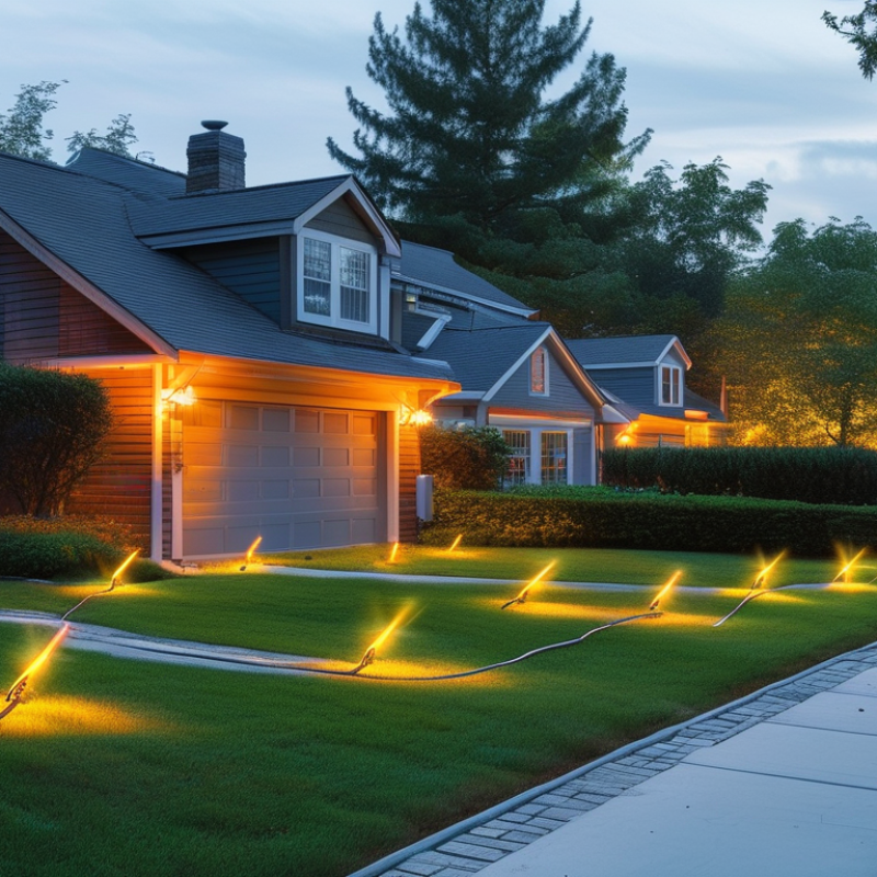
A dim final fixture usually indicates voltage drop, not a defective lamp. The cable carries current to every fixture, and resistance increases with distance. The National Electrical Code 2023, Section 210.19(A), recommends limiting branch-circuit voltage drop to 3%, with 5% for the complete circuit. At 12 volts, even a small loss becomes visible.
Check voltage at three points: the transformer output, the first fixture, and the last fixture. Measure under load, after the lights have operated for several minutes. For example, five 10-watt fixtures draw about 4.2 amps at 12 volts. A 100-foot, 16-AWG copper run has roughly 0.8 ohms of round-trip resistance. That can create a voltage loss near 3.4 volts. The last light may receive only 8.6 volts. It will look weak.
Use shorter branches or heavier cable when the measured loss exceeds the design target. Split long runs instead of placing every fixture on one continuous line. Also inspect buried connectors for moisture, loose terminals, and green corrosion. A professional field check should compare transformer voltage with the circuit energized, not disconnected. IES Lighting Handbook guidance supports evaluating lighting performance under actual operating conditions, yet installers sometimes test only at the panel. That shortcut can mislead. Confirm the transformer’s rated output, total wattage, timer settings, and photocell connections. A warm connector may reveal resistance that a visual inspection misses.
A dim final fixture usually indicates excessive voltage drop, not a defective lamp. Measure voltage at the transformer, then measure it at the last fixture under load. I have seen a system start near 12.5 volts and fall below 10.5 volts at the far end. That difference is visible.
Cable length matters because current travels out and back. Use this formula: voltage drop equals current multiplied by resistance and total circuit length. For example, a 100-foot run carrying 2 amps through 16 AWG copper can lose about 1.6 volts. The calculation uses approximately 4.016 ohms per 1,000 feet at 25°C, a value consistent with NEC Chapter 9, Table 8 resistance data. The fixture may receive only 10.4 volts.
Thicker cable has lower resistance. Moving from 16 AWG to 12 AWG can substantially reduce the loss, especially on long runs. The National Electrical Code, NFPA 70, Informational Note No. 4, identifies 3% branch-circuit and 5% total voltage drop as reasonable design targets. Low-voltage lighting often needs closer attention because the system begins with only 12 volts. Split long circuits into shorter branches, reduce the load on each branch, or increase conductor size. Check every connector too. A loose, wet, or corroded connection can create a small resistance that becomes a visible dim spot. My first measurement is rarely the final answer; temperature, actual fixture wattage, and hidden splices can change the result.
When 12V landscape lights dim near the end of a run, start at the transformer. Set a digital multimeter to AC voltage, not DC. With the lights operating, test the transformer’s output terminals. Compare the reading with its rated setting. A reading that looks normal without a load may fall sharply when every lamp is connected. That detail is easy to miss.
Measure voltage at the first fixture, then at the dimmest fixture. Keep the lights switched on during both tests. A healthy circuit may show a small drop, but a large difference suggests excessive resistance. Check loose wire nuts, corroded connectors, damaged insulation, and undersized cable. Moisture inside a connector can create a surprisingly weak connection. Test each section separately if the circuit has several branches.
The total lamp wattage may also exceed the transformer’s practical capacity. Remove one fixture temporarily and measure again. If the far-end voltage improves, the circuit may need shorter runs, heavier cable, or separate branches. Use the transformer’s instructions for acceptable voltage and load limits. Switch off power before opening connections, and use outdoor-rated components. I have learned that replacing the transformer too quickly can hide a poor splice. A quick test can mislead. Record every voltage reading, because memory is less reliable than a written measurement.
When 12V landscape lights dim near the end of a run, voltage drop is often the cause. A long cable creates resistance, especially with thin conductors and many fixtures. I once blamed a weak transformer before checking the cable path. That shortcut was wrong. Measure voltage at the transformer and at the final light while the system operates. A large difference confirms a wiring problem.
Balance the light loads across separate runs instead of placing every fixture on one cable. Count the total wattage in each section, then compare it with the available transformer capacity. A heavily loaded first section can leave little voltage for distant fixtures. Splitting the path into two shorter circuits usually improves brightness. Keep each run practical. Extra cable length can quietly increase losses.
Improve every connection along the route. Loose wire nuts, corrosion, and poorly sealed junctions add resistance. Open each accessible connection and inspect for moisture, darkened copper, or brittle insulation. Clean damaged conductors and use outdoor-rated, waterproof connectors. Do not simply twist wires together. Check polarity and retest under the full lighting load. A thicker cable may help, but only after confirming the connections and load balance. In my experience, troubleshooting in a hurry causes missed faults. Marking each circuit and recording voltage readings makes the next repair more reliable.
When 12V landscape lights become dim near the end of a run, inspect damaged components before replacing the entire system. I once found a cracked connector hidden beneath damp mulch. Its corrosion created resistance and reduced voltage at the final fixture. Turn off the power, then examine connectors, cable insulation, sockets, and fixture housings. Replace melted connectors, cut cable sections, and water-damaged fixtures with correctly rated parts. Do not rely on a twisted-wire repair.
Measure voltage at the power supply and at the first, middle, and last lights. A reliable multimeter makes this comparison clearer than visual inspection. Record each reading before changing anything. If voltage drops sharply at one connection, repair that point and test again. Loose terminals often look acceptable but fail under load. I have occasionally blamed the cable when the real problem was a poorly seated socket. That mistake wastes time.
After replacing damaged components, run every light for at least fifteen minutes. Check the final fixture at dusk, when uneven brightness is easier to notice. Each light should produce a steady, similar output without flickering or excessive heat. Recheck the last connector after the system warms up. Small voltage differences may remain, especially on long runs, but a visibly weak final light needs further testing. Keep notes of voltage readings and repairs for future maintenance.
This calculated example assumes a 12V source, ten 4W fixtures drawing approximately 3.33A, and a 100-foot one-way run using 12 AWG copper cable. The healthy-run values reflect normal cable resistance. The damaged-connection values show the effect of adding 0.30Ω of resistance after the 50-foot point, which can make fixtures at the end of the run noticeably dimmer. Replace damaged connectors or cable sections, then verify that voltage remains reasonably even at each fixture position.
Excessive voltage drop is often the cause. A long cable loses voltage as current travels out and back. A system may begin near 12.5 volts and fall below 10.5 volts. That difference can make the last fixture visibly weak.
Set a digital multimeter to AC voltage. Keep the lights operating during every measurement. Test the transformer output first. Then test the first fixture and the dimmest fixture. Write down each reading. Memory fails.
Longer cable creates more resistance. The current travels through the outgoing and returning wires. A 100-foot run carrying 2 amps can lose about 1.6 volts with 16 AWG copper. The far fixture may receive only about 10.4 volts.
Yes, thicker cable usually has lower resistance. Changing from 16 AWG to 12 AWG can reduce losses on long runs. This matters more when several fixtures share one cable. Cable size alone is not magic.
Inspect every accessible connection along the route. Look for loose terminals, corrosion, moisture, or darkened copper. Damaged insulation can also cause trouble. Use outdoor-rated, waterproof connectors. Do not simply twist wires together.
Yes, total lamp wattage may exceed the transformer’s practical capacity. Count the wattage on each branch. Temporarily remove one fixture and measure the far-end voltage again. If brightness improves, the circuit may carry too much load. My first transformer suspicion was wrong once.
Splitting a long path into shorter branches often improves brightness. Balance the fixture wattage across separate runs. Avoid placing every light on one heavily loaded cable. Shorter paths usually create less voltage loss. Keep each branch practical.
Replace it only after testing output voltage under full load. A normal unloaded reading can fall sharply when all fixtures operate. Check wiring, connections, cable size, and load balance first. A new transformer may hide a poor splice. Test before replacing.
If you are wondering, “why are my 12v landscape lights dim at the end of the run,” the most common cause is voltage drop. Long cable runs, undersized wire, excessive light loads, and loose or corroded connections can reduce the power reaching fixtures farthest from the transformer. Begin by checking the cable length and wire gauge, then use a multimeter to measure voltage at the transformer and at several points along the circuit. A significant difference can confirm that the wiring system needs improvement.
You may also need to test the transformer’s output and make sure the connected lights do not exceed its capacity. Balance the light load across separate circuits when possible, tighten or replace weak connections, and inspect the cable for damage. If individual fixtures, connectors, or sections of wire are defective, replace them with suitable components. After repairs, measure the voltage again and confirm that all lights produce a consistent, even level of brightness.